Wednesday, August 07, 2024

Simple Fix for WSL2 and GlobalProtect VPN

 I ran across this today and am documenting it in case it helps others.  To make WSL work with GlobalProtect VPN, add the following into a file called "wslconfig" under your %USERPROFILE%\ directory:

[wsl2]

networkingMode=mirrored

dnsTunneling=true


Then in a powershell, run the following:

wsl --shutdown

wsl --update


Now when you start wsl, it should have network access. 

Friday, April 14, 2023

Crkbd keymap from configurator json and using kb2040 microcontroller


I wanted to document this for anyone else who's not super familiar with qmk and wants to get a setup working with the kb2040.   Here are the steps I followed:

Design a layout on QMK Configurator

https://config.qmk.fm/#/crkbd/rev1/LAYOUT_split_3x6_3

Export the json, e.g. to ~/Downloads/my_custom_keymap.json

Setup QMK on your computer

sudo apt install python3-pip

pip3 install qmk

qmk setup

And setup the keymap

We copy the default keymap directory and replace keymap.c with one based on our json.

cd ~/qmk_firmware/keyboards/crkbd/keymaps

cp default foo

cd foo

mv keymap.c keymap.c.defaultl

qmk json2c ~/Downloads/my_custom_keymap.json > keymap.c

Then build the firmware and flash it!

The secret sauce here was "CONVERT_TO=kb2040" - I didn't have to modify anything else, it just did what was needed to make this compatible with the kb2040 microcontrollers.

qmk flash -kb crkbd -km foo -e CONVERT_TO=kb2040

Press the boot button on the mcu, plug it into usb, and it should flash.  You can run it again for the second half of the kb, or just drag the .df2 over to it.

Thursday, March 30, 2023

Installing VS Code on Raspberry Pi and Ubuntu

 The aarch64 build of VS Code is available in Raspberry Pi OS repositories to bi installed directly with "apt install code", but the Ubuntu repos only have x86 and x86_64 versions of code.  So we need to manually install code - once we install the .deb package, it adds the Microsoft repo for us to keep it up to date:

Look for and download the latest arm64 package here:
https://packages.microsoft.com/repos/code/pool/main/c/code/

Then install it with dpkg:
sudo dpkg --install ~/Downloads/code*arm64.deb

Afterward, apt will keep it up to date.

Thursday, March 02, 2023

First tests with the new Amp Ripper 4k

I've use the Amp Ripper 3000, from kickstart-design, in previous projects - it is one of the highest quality, most simple to use charger/boost converters available for powering Raspberry Pi and other 5v projects.  It's plug-and-play from charger to battery to Raspberry Pi with enough power to run the Pi 4 and has a low-voltage pin to signal when the battery gets low.  And its one of the few solutions supporting pass-through-charging so it's suitable for a UPS.

The Amp Ripper 4000 (Kickstarter link) builds on the 3k with loads of improvements:

  • Increased 4 amp maximum current supply for more demanding setups.
  • I2C reporting of charging/battery voltage, battery percentage, charge/discharge rates via a MAX17084 chip.
  • Several large VOUT solder connections.
  • Support for a wide range of charging voltages:  5-14v!  Charge from 12v automotive systems, solar, etc.
  • Battery temperature thermistor support.
  • Configurable charging current if you'r adventurous enough to replace a surface mount resistor.
I'll be testing the overall performance of the AR 4k and writing code to query battery values from its i2c.  See below for example code to use in your projects.  Testing goals:

  • Power performance - Does it run an Intel Compute Stick m3? (YES!)
  • Reading battery charge stats via i2c using a pi 4 and python.
  • Reading battery charge stats via i2c using a pi pico and micropython.
  • Verifying battery percentage estimates and high/low cutoff voltages.
This is my test setup - a 12ah (1s6p) li-ion pack.  I'll add a disconnect for the battery when I get some BT2.0 plugs in the mail, but for now it's directly soldered to the AR 4k board.  

Be careful about using plugs in line with your batteries that aren't rated for 5+ amp.  I've had issues in the past  using JT/JXT connectors and voltage drop across them. 

Raw Power Performance

I have an Intel Compute Stick M3 that is my benchmark for any USB 5v supply.  It's finicky and will bootloop if the supply can't keep up so generally it has to be run from a wall wart.  The AR3k couldn't run it without hangs. 

The AR4k is working flawlessly here.  I got a youtube video going in chrome and started playing Hollow Knight in Steam while monitoring with top and no hangs!  I alternated between charging discharging and let it run for a couple hours on battery with no issues.

Reading battery charge stats via i2c  

Using a Pi 4 and Python

Wiring Guide


Example Code For Reading Battery Voltage and Percent

The AR4k uses a MAX17048 Li-Ion fuel gauge chip.  It will need at least one charge/discharge cycle before it correctly reports battery "cell_percent".  I'll update this with more specifics as my current project evolves.  There is an easy to use library from Adafruit for this chip that works well with the AR4k.

This is working on the latest (as of March 2023) Raspberry PI OS 32 bit.  It should be the same for RP OS 64 bit, but you may need different libraries with Ubuntu or other distros.  

Setup:
$ pip3 install adafruit-circuitpython-max1704x i2c-tools
$ sudo usermod -a -G dialout your_acct_name
$ reboot

Verify you can see the i2c device.  You should see a 36 listed for the max17048 chip using i2cdetect:
$ i2cdetect -y 1
...
30: -- -- -- -- -- 36 -- ...
...

If that works, you should be able to query the battery voltage:
$ python
>>> import time
>>> import board
>>> import adafruit_max1704x
>>> i2c = board.I2C()
>>> max17 = adafruit_max1704x.MAX17048(i2c)
>>> time.sleep(1)
>>> print(max17.cell_voltage)
3.54625
>>> print(max17.cell_percent)
35.69921875
>>>

The time.sleep(1) is needed if you put this in a script.  You'll see cell_voltage reported and cell_percent both reported as "0.0" if you query them immediately after the max17= line.

Notes for Ubuntu 22.10

If you're using Ubuntu 22.10 on your Pi, there are a couple extra steps to get started - we need to install the raspberry pi gpio library and add our account to the dialout group for access to the /dev/i2c* devices:

$ apt install python3-pip python3-rpi.gpio
$ sudo usermod -a -G dialout your_acct_name
$ reboot

Enabling Safe-Shutdown on Low Voltage

This is a pretty standard feature intended to power off the pi before the battery is completely dead so that it can be shut down cleanly, avoiding file-system corruption from a hard-power-off.  

The MAX1704x can be set to toggle the INT pin at a configured voltage, or we can use the LBO pin to trigger at 3.3v.  We can trigger a shutdown of the Pi by connecting the pin to a GPIO pin and updating config.txt.  - Additional hardware is needed to actually turn off the PSU, so an update will be made here once I sort that out.

To enable auto shutdown on the pi, edit /boot/firmware/config.txt and add the following line at the bottom:

dtoverlay=gpio-shutdown,gpio_pin=4,active_low=1,gpio_pull=up,debounce=1000

NOTE - I need to verify this.  I'll update in a few days when this is confirmed to be exactly correct.

Implementing a kernel module to make the power supply and battery appear as a laptop battery for the Raspberry Pi

This is work in progress.  There is a


Monday, October 10, 2022

Micropython - Driving an LCM4004A LCD with dual HD44780 (clone) driver chips


This is the display I'm using:

There are a few vendors for these 40 column x 4 row displays, all using clones of the Hitachi HD44780 controller:

These have a character pallet built in and have memory for 8 custom characters when needed.  And they have memory/wiring to support 80 characters on a display, so this 4004 display with 160 characters uses two drivers.  They share the same Data, RS, RW pins, but each have a separate enable pin to instruct them separately when writing to different lines of the display.

I didn't find any libraries specifically for this display, most of them are for 2004 or 4002 displays with a but this one from Adafruit gets pretty close - it's for the correct driver chip, but needed to be adapted to support two driver chips.  I ended up completely gutting this to get stuff working without the extra code, but adapted the setup sequence and write8 functions from here:


I'm using an Arduino Nano Connect RP2040 here, so the pins will be a little different for a PI Pico or other chip. 

Generally, the way this works is we:
  • Define our pins
  • Initialize some globals with the values for specific instructions that the contorller understands
  • Call the initialize function to turn the display on
  • Subsequently use the "write8" function to write characters to the display.

What's left to do?
  • Figure out how to control the cursor and write to specific locations on the display.
  • Figure out how to turn on the backlight.
  • Get contrast control working.  I tried to do this with a 10k pot, but the display isn't responding.
  • Adapt this module to work with the fbconsole library for a fun terminal.


import time
from machine import Pin

D4 = Pin(26, Pin.OUT)
D5 = Pin(27, Pin.OUT)
D6 = Pin(28, Pin.OUT)
D7 = Pin(29, Pin.OUT)
E1 = Pin(12, Pin.OUT)
E2 = Pin(13, Pin.OUT)
RS = Pin(5, Pin.OUT)

# Commands
LCD_CLEARDISPLAY = 0x01
LCD_RETURNHOME = 0x02
LCD_ENTRYMODESET = 0x04
LCD_DISPLAYCONTROL = 0x08
LCD_CURSORSHIFT = 0x10
LCD_FUNCTIONSET = 0x20
LCD_SETCGRAMADDR = 0x40
LCD_SETDDRAMADDR = 0x80

# Entry flags
LCD_ENTRYRIGHT = 0x00
LCD_ENTRYLEFT = 0x02
LCD_ENTRYSHIFTINCREMENT = 0x01
LCD_ENTRYSHIFTDECREMENT = 0x00

# Control flags
LCD_DISPLAYON = 0x04
LCD_DISPLAYOFF = 0x00
LCD_CURSORON = 0x02
LCD_CURSOROFF = 0x00
LCD_BLINKON = 0x01
LCD_BLINKOFF = 0x00

# Move flags
LCD_DISPLAYMOVE = 0x08
LCD_CURSORMOVE = 0x00
LCD_MOVERIGHT = 0x04
LCD_MOVELEFT = 0x00

# Function set flags
LCD_8BITMODE = 0x10
LCD_4BITMODE = 0x00
LCD_2LINE = 0x08
LCD_1LINE = 0x00
LCD_5x10DOTS = 0x04
LCD_5x8DOTS = 0x00


def delay_microseconds(microseconds):
# Busy wait in loop because delays are generally very short (few microseconds).
end = time.time() + (microseconds/1000000.0)
while time.time() < end:
pass


def write8(value, enable_pin, char_mode=False):
"""Write 8-bit value in character or data mode. Value should be an int
value from 0-255, and char_mode is True if character data or False if
non-character data (default).
"""
print('write8', f'{value:#010b}', enable_pin, char_mode)
# One millisecond delay to prevent writing too quickly.
delay_microseconds(1000)

# Set the character/data bit
RS.value(1 if char_mode else 0)

# Write the Upper 4 bits
D4.value(((value >> 4) & 1) > 0)
D5.value(((value >> 5) & 1) > 0)
D6.value(((value >> 6) & 1) > 0)
D7.value(((value >> 7) & 1) > 0)

enable_pin.off()
delay_microseconds(1)
enable_pin.on()
delay_microseconds(1)
enable_pin.off()
delay_microseconds(1)

# Write the Lower 4 bits
D4.value((value & 1) > 0)
D5.value(((value >> 1) & 1) > 0)
D6.value(((value >> 2) & 1) > 0)
D7.value(((value >> 3) & 1) > 0)

enable_pin.off()
delay_microseconds(1)
enable_pin.on()
delay_microseconds(1)
enable_pin.off()
delay_microseconds(1)

def clear():
print('Clear')
write8(LCD_CLEARDISPLAY, E1) # command to clear display
delay_microseconds(3000) # 3000 microsecond sleep, clearing the display takes a long time
write8(LCD_CLEARDISPLAY, E2)


def initialize():
print('Initializing')
# Initialize display control, function, and mode registers.
displaycontrol = LCD_DISPLAYON | LCD_CURSOROFF | LCD_BLINKOFF
displayfunction = LCD_4BITMODE | LCD_1LINE | LCD_2LINE | LCD_5x8DOTS
displaymode = LCD_ENTRYLEFT | LCD_ENTRYSHIFTDECREMENT

for enable_pin in E1, E2:
write8(0x33, enable_pin)
write8(0x32, enable_pin)
# Write registers.
write8(LCD_DISPLAYCONTROL | displaycontrol, enable_pin)
write8(LCD_FUNCTIONSET | displayfunction, enable_pin)
write8(LCD_ENTRYMODESET | displaymode, enable_pin) # set the entry mode
clear()


if __name__ == '__main__':
initialize()
# Initialize the display.
for char in 'Hello World':
write8(ord(char), E1, True)
for char in 'Foo Bar! +~!123':
write8(ord(char), E2, True)


Saturday, August 13, 2022

Micropython - Modifying fbconsole.py to support keystroke injection with os.dupterm

 This is something I needed to make an interactive micropython terminal without using the serial connection to interact with it.  E.g.  a separate library handles keyborad scanning using the pi pico pins and when a keypress is registered, a callback function is used to pass the dupterm instance.  Since I want to use fbconsole to display the console on a screen, it made sense to add the needed bits to the fbconsole library to support passing in the keystrokes:


Usage:

In our display module:

display = ssd1306.SSD1306_I2C(128, 64, i2c_list[0], 0x3c)

scr = FBConsole(display)
os.dupterm(scr)

And for a callback function, we can use something like this:

STREAM = oled_fb.scr
keeb.activate(STREAM.inject) # setup the callback

To pass in single or multiple characters, you can use the inject method.  You'll see them appear in the terminal when the function is called:

STREAM.inject('1 + 1')
STREAM.inject(b'\r')


fbconsole.py Modifications:

Within fbconsole.py, we add a couple imports, constants, and define self._data in __init__:

import framebuf
import uio
import os

_MP_STREAM_POLL = const(3)
_MP_STREAM_POLL_RD = const(0x0001)
class FBConsole(uio.IOBase):
def __init__(self, fb, bgcolor=0, fgcolor=-1, width=-1, height=-1, readobj=None):
self._data = bytearray()
self.readobj = readobj

And methods in the class:

def inject(self, data):
self._data += data

if hasattr(os, 'dupterm_notify'):
os.dupterm_notify(None)

def read(self, sz=None):
d = self._data
self._data[:] = b''
return d

def ioctl(self, op, arg):
if op == _MP_STREAM_POLL:
if self._data:
return _MP_STREAM_POLL_RD

And finally modify the readinto method. 

# def readinto(self, buf, nbytes=0):
# if self.readobj != None:
# return self.readobj.readinto(buf, nbytes)
# else:
# return None

def readinto(self, buf):
if not self._data:
return None
b = min(len(buf), len(self._data))
buf[:b] = self._data[:b]
self._data = self._data[b:]
return b

Finally, in addition to regular numbers, letters, and symbols, you'll need a few ascii codes to pass in enter, backspace, etc as well as ctrl+key cobmos:


ASCII_CODES = {
'_bksp': b'\b',
'_entr': b'\r',
'_tab': b'\t',
}

CTRLED = {
'a': b'\x01', # ctrl + a
'b': b'\x02',
'c': b'\x03',
'd': b'\x04',
}

I'll do a followup article with more info on ctrl and other special characters.  We should be able to pass in arrows to move the cursor, etc. 

Finally, this article will be updated with a link to the complete code soon. 

Reference:


Tuesday, July 26, 2022

RP2040 Micropython PIO - Part 4 - Using IRQ to signal when pins changes have been pushed!

I'm delighted that this worked exactly as it seemed it ought to.  Just like we did in Part 3, we track the pins states and only push them when there's been a change.  But now, when we push the changed pins, we toggle the irq. 

When we initialize the state machine, we bind a function, "printFromGet" to the state machine irq. When the irq is toggled, this function is called, and a pointer to the state machine is passed to the function.  Then we can call sm.get() to read the new pins values.   This is fantastic because python doesn't need to spin checking the pins using the gpio library wasting cpu cycles.  When we press a key, python is detoured momentarily to our needed function to handle the pin press, and once it returns, python can resume whatever else it was working on!

Here's a more complete code from the last couple examples. 

import safety_pin
import pio_junk
from machine import Pin
import rp2
import time

COUNT = 0

def initPinsAsIn(direction=Pin.PULL_UP):
for n in range(32):
try:
Pin(n, Pin.IN, direction)
except:
print("Couldn't initialize pin:", n)

def printFromGet(sm):
global COUNT
out = sm.get()
print(f'{COUNT} - {out:>032b}')
COUNT += 1

@rp2.asm_pio( set_init=[PIO.IN_HIGH]*32 )
def irq_pins_changes():
mov(y, pins)
#in_(y, 32)
mov(isr, y)
push()

wrap_target()
label("read loop")
mov(x, pins)

jmp(x_not_y, "exit read loop")
jmp("read loop")
label("exit read loop")
mov(isr, x)
mov(y, x)
push()
irq(1)

wrap()

if __name__ == '__main__':
print('In Main Now')
initPinsAsIn()

sm = rp2.StateMachine(0, irq_pins_changes,
freq=2000, in_base=Pin(0))
sm.irq(printFromGet, 0)

sm.active(1)
for n in range(10):
out = sm.get()
print(f'{n}, {out:>032b}')
sm.active(0)

The last thing I might want to do is sort of look up which pin changed and push an integer value corresponding with the addr of the changed pin so each time I do a get() in python, I get the number of the changed pin.  

Monday, July 25, 2022

RP2040 Micropython PIO - Part 3 - Pushing pins only on changes

 In order to check for changes to the pins, each time we read the pins values, we can compare them to previous values stored in the x or y scratch registers. 

So the statemachine records the pin state in y when it starts, pushes y so python has the initial state as well, and then the state machine keeps checking the pins until the pin values cached in x aren't equal to y.  Then it pushes x, copies x to y, and starts checking again. 

for n in range(32):
try:
Pin(n, Pin.IN, Pin.PULL_UP)
except:
print("Couldn't initialize pin:", n)

@rp2.asm_pio( set_init=[PIO.IN_HIGH]*32 )
def echo_pins_changes():
mov(y, pins)
#in_(y, 32)
mov(isr, y)
push()

wrap_target()
label("read loop")
mov(x, pins)

jmp(x_not_y, "exit read loop")
jmp("read loop")
label("exit read loop")
mov(isr, x)
mov(y, x)
push()

wrap()

sm = rp2.StateMachine(0, pio_junk.echo_pins_changes,
freq=2000, in_base=Pin(0))

sm.active(1)
for n in range(10):
out = sm.get()
print(f'{n}, {out:>032b}')
sm.active(0)

Next step is setting an irq to tell python it's time to pull a value from the fifo.  

And maybe later some time, we can implement matrix scanning!  I'm not too sure how that would work since we'd need to potentially track the state of more than 32 keys...  maybe we'd use separate state machines for each row of the keyboard!

Sunday, July 24, 2022

RP2040 Micropython PIO - Part 2 - Reading all the pins!

 The next thing I wanted to get working with PIO was reading the pin values.   I struggled with this until I realized that I needed to initialize the pins and set them to pull_up before starting the state machine.  Anyway, here's an example reading all available pins and returning their states on the fifo:

@rp2.asm_pio( set_init=[PIO.IN_HIGH]*32 )
def echo_pins():
wrap_target()
in_(pins, 32)
push()

set(x, 31) # call nop 32 times to slow things down
label("aloop")
nop() [31]
jmp(x_dec, "aloop")

wrap()

for n in range(32): # Initialize all the pins with PULL_UP
try:
Pin(n, Pin.IN, Pin.PULL_UP)
except:
print("Couldn't initialize pin:", n)

sm = rp2.StateMachine(0, pio_junk.echo_pins,
freq=2000,
in_base=Pin(0))

sm.active(1)
for n in range(10): # pull pin states from the fifo ten times!
out = sm.get()
print(f'{n}, {out:>032b}')
sm.active(0)

And the output looks like the following.  Some of the bits change as I press keys on the keyboard:

>>>
MPY: soft reboot
Checking Safety Pin 25...
In Main Now
Couldn't initialize pin: 30
Couldn't initialize pin: 31
0, 00111110111111111111101111111011
1, 00111110111111111111101111111011
2, 00111110111111111111101111111011
3, 00111110111111111111101111111011
4, 00111110110101011111101101111011
5, 00111110110101011111101101111011
6, 00111110110101011111101101111011
7, 00111110111111111111101111111011
8, 00111110111111111111101111111011
9, 00111110110101011111101101111011
MicroPython v1.19.1 on 2022-06-18; Arduino Nano RP2040 Connect with RP2040
Type "help()" for more information.
>>>

In Part 3, we'll track the pin states and  only output a value when there is a change.  

And in Part 4, we'll use an irq to trigger a python function only when there is a key press event so we don't need to keep a cpu core busy watching for button presses. 

Saturday, July 23, 2022

RP2040 Micropython PIO - Part 1 - Blinking nop, jmp, and .side experiments!

 I'm working on incrementally adding complexity to PIO programs to learn how to use them.  Here are a few examples.  Note that I'm using Pin 6 for the LED on the Arduino Connect Nano RP2040 board.  I think the pin is different for the Pi Pico.

Most Simple Blinking the LED:

The most simple classic blinking example - toggle a pin on and off with the slowest freqency (2000) and a bunch of nop waits to slow the blinking down enough that we can see it!

@rp2.asm_pio(set_init=rp2.PIO.OUT_LOW)
def blink():
wrap_target()
set(pins, 1) [31]
nop() [31]
nop() [31]
nop() [31]
nop() [31]
set(pins, 0) [31]
nop() [31]
nop() [31]
nop() [31]
nop() [31]
wrap()

# sm = rp2.StateMachine(0, pio_junk.blink, freq=2000, set_base=Pin(6))
# sm.active(1)


Blinking the LED Using sideset and jmp for more nop:

In this example, we use sideset to toggle the LED pin on and off and jmp to loop for more nop.

Normally, in each PIO assembled instruction, 5 bits are available to specify length of wait, so 0-31 wait cycles.  But when we enable sideset, 2 (or more??) bits are used to specify the sideset value.  In this case, we use Pin 6 (the LED) as the sideset pin, and we have a max wait of 7 (three bits). 

This speeds up the program execution without a bunch more nop calls.  So we can count on the x scratch register to repeatedly call nop with a jmp and slow the blinking enough that we can see it, like before using sideset and the longer [31] wait.

@rp2.asm_pio(sideset_init=rp2.PIO.OUT_LOW)
def side_blink():
wrap_target()
set(x, 31).side(0x0)
label("aloop")
nop() [7]
jmp(x_dec, "aloop")

set(x, 31).side(0x1)
label("bloop")
nop() [7]
jmp(x_dec, "bloop")
wrap()

# sm = rp2.StateMachine(0, pio_junk.side_blink, freq=2000, sideset_base=Pin(6))
# sm.active(1)


Up next...

I'm trying to read the value of all of the pins and put the values into the fifo to be used by the Micropython program...

Micropython - Safety pin to avoid soft-bricking

 I ran into an issue on an Arduino Connect Nano RP2040 board this last week where I got some code in main.py that caused micropython to hang without functional serial or shared drive, so I had no way to change the code and fix it. 

It was a little difficult to fix this.  A few things I tried:

  • Re-flash the micropython uf2 - this doesn't wipe the main.py and other code, so the problem remains.
  • Flash circuitpython uf2 - circuitpython stores code at a different addr and works perfectly when flashed, but when you put micropython back, the old broken main.py remains.  I even tried to dd a large random data file to the circuitpython shared folder, but somehow it didn't overwrite the micropython content!
  • Flash the various nuke uf2 files - It seems that these are all set up for the pi pico, which has 4MB of storage.  The arduino board has 8MB of storage and the area micropython uses is unaffected. 
What did finally work!
  • Flash the OpenMV customized version of Micropython.  It didn't load the main.py and exposed the same memory/file share that micropython uses so I was able to rename the broken main.py and flash standard Micropython back onto the board to resume working on it!
  • https://github.com/openmv/openmv/
And how to avoid this in the first place - It's surprisingly easy to hang micropython when experimenting with PIO and other stuff with blocking functions. The solution I'm using now is to source a file that checks if a pin is grounded.  If it is, it calls sys.exit() so the program quits instead of continuing and triggering another hang. 

main.py:

import saftey_pin
...
...


safety_pin.py:

from machine import Pin
import time
import sys

PIN_NUM = 25
SAFETY_PIN = Pin(PIN_NUM, Pin.IN, Pin.PULL_UP)

print(f"Checking Safety Pin {PIN_NUM}...")
time.sleep(.1)
if not SAFETY_PIN.value():
    print("PIN Shorted to Ground!")
    print("Aborting loading and quitting.")
    sys.exit()


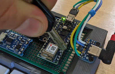
 To use it, I put a key between the two pins shown here and plug the board into the usb port:


Friday, July 08, 2022

Micropython - Keyboard library with chording, layers, etc.

 I'm working on a project to build an interacive terminal using micropython, and a component of that is checking for button presses and translating them to keys to be used to control the terminal or however that works.  

I've made a couple of attempts at keyboard firmwares in the past and changed strategies this time from key-focused to event-focused - events start when a key is pressed and terminate after either a hold timer or key that is part of the event is released.  

Based on the numbers of keys in the event, their functions, and hold duration, we can figure out the correct keyboard key to be returned.  

Examples to consider:

  • Chords can map combinations of keys to letters, numbers, or symbols,
  • A single key, if held for some duration, can trigger a layer shift and then subsequent keys or combinations of keys can result in letters, numbers, etc from that layer. 
  • Short taps result in a number, letter, etc. 
Anyway, this might be a helpful template for anyone trying to do something similar:

https://github.com/a8ksh4/MicroNote/blob/main/keeb.py

Monday, April 27, 2020

Setting up TNC-Pi9k6 - Raspberry Pi Hat with Pi 4

Notes from my setup that others might find helpful:

Using latest build of raspbian

Ran os updates:
sudo apt update; sudo apt upgrade

Ran firmware update:
sudo rpi-update

Detecting the TNC and running getparams first time:

Following the manual here as it's for this particular hardware: https://www.wvcarc.com/p/tnc-96k-resources.html
And additional help from this manual since it has much more information: http://www.tnc-x.com/TNCPi.pdf

Serial Port - it should be on /dev/serial0. To enable it, do:
sudo raspi-config
Select option 5 for Interfacing options
Select option 6 for Serial
Say "no" to the login shell question.
Say "yes" to serialport hardware question.
Reboot
Now you should see output when you do "pitnc_getparams /dev/serial0 0"

Software Setup

Following this guide for software setup: https://dl1gkk.com/setup-raspberry-pi-for-ham-radio/
Skipped the direwolf stuff for now since I'm using the TNC